Sabtu, 14 September 2013

Silinder Pneumatic

2.1.            Silinder Pneumatic
Aktuator adalah bagian keluaran untuk mengubah energi suplai berupa udara bertekanan menjadi energi kerja yang dimanfaatkan. Sinyal keluaran dikontrol oleh sistem kontrol dan aktuator bertanggung jawab pada sinyal kontrol melalui elemen kontrol terakhir.
 Aktuator pneumatik dapat digolongkan menjadi 2 kelompok : 
1. Gerakan lurus (gerakan linear) :
a. Silinder kerja tunggal.
b. Silinder kerja ganda.
2. Gerakan putar :
a. Motor udara
b. Aktuator yang berputar (ayun)


Simbol-simbol aktuator linear sebagai berikut :
Tabel 2.1. simbol aktuator linear
Simbol aktuator gerakan putar :
Tabel 2.2. simbol aktuator putar
2.2.1.    Silinder Kerja Tunggal
2.2.1.1. Konstruksi
Silinder kerja tunggal mempunyai seal piston tunggal yang dipasang pada sisi suplai udara bertekanan. Pembuangan udara pada sisi batang piston silinder dikeluarkan ke atmosfir melalui saluran pembuangan. Jika lubang pembuangan tidak diproteksi dengan sebuah penyaring akan memungkinkan masuknya partikel halus dari debu ke dalam silinder yang bisa merusak seal. Apabila lubang pembuangan ini tertutup akan membatasi atau menghentikan udara yang akan dibuang pada saat silinder gerakan keluar dan gerakan akan menjadi tersentak-sentak atau terhenti. Seal terbuat dari bahan yang fleksibel yang ditanamkan di dalam piston dari logam atau plastik. Selama bergerak permukaan seal bergeser dengan permukaan silinder.

Gambar konstruksi silinder kerja tunggal sebagai berikut :    
Gambar 2.10. gambar silinder

2.2.1.2. Prinsip Kerja
Dengan memberikan udara bertekanan pada satu sisi permukaan piston, sisi yang lain terbuka ke atmosfir. Silinder hanya bisa memberikan gaya kerja ke satu arah . Gerakan piston kembali masuk diberikan oleh gaya pegas yang ada didalam silinder direncanakan hanya untuk mengembalikan silinder pada posisi awal dengan alasan agar kecepatan kembali tinggi pada kondisi tanpa beban.
Pada silinder kerja tunggal dengan pegas, langkah silinder dibatasi oleh panjangnya pegas . Oleh karena itu silinder kerja tunggal dibuat maksimum langkahnya sampai sekitar 80 mm.
2.2.1.3. Kegunaan
Menurut konstruksinya silinder kerja tunggal dapat melaksanakan berbagai fungsi gerakan , seperti :
1.    Menjepit benda kerja
2.    Pemotongan
3.    Pengeluaran
4.    Pengepresan
5.    Pemberian dan pengangkatan.
2.2.1.4. Macam-Macam Silinder Kerja Tunggal
Ada bermacam-macam perencanaan silinder kerja tunggal termasuk :
1.      Silinder membran (diafragma)
2.      Silinder membran dengan rol


2.2.2.    Silinder Ganda
2.2.2.1. Konstruksi
Konstruksi silinder kerja ganda adalah sama dengan silinder kerja tunggal, tetapi tidak mempunyai pegas pengembali. Silinder kerja ganda mempunyai dua saluran (saluran masukan dan saluran pembuangan). Silinder terdiri dari tabung silinder dan penutupnya, piston dengan seal, batang piston, bantalan, ring pengikis dan bagian penyambungan. Konstruksinya dapat dilihat pada gambar berikut ini :
Gambar 2.11. kontruksi silinder kerja ganda
Biasanya tabung silinder terbuat dari tabung baja tanpa sambungan. Untuk memperpanjang usia komponen seal permukaan dalam tabung silinder dikerjakan dengan mesin yang presisi. Untuk aplikasi khusus tabung silinder bisa dibuat dari aluminium , kuningan dan baja pada permukaan yang bergeser dilapisi chrom keras. Rancangan khusus dipasang pada suatu area dimana tidak boleh terkena korosi.
Penutup akhir tabung adalah bagian paling penting yang terbuat dari bahan cetak seperti aluminium besi tuang. Kedua penutup bisa diikatkan pada tabung silinder dengan batang pengikat yang mempunyai baut dan mur.
Batang piston terbuat dari baja yang bertemperatur tinggi. Untuk menghindari korosi dan menjaga kelangsungan kerjanya, batang piston harus dilapisi chrom.
Ring seal dipasang pada ujung tabung untuk mencegah kebocoran udara. Bantalan penyangga gerakan batang piston terbuat dari PVC, atau perunggu. Di depan bantalan ada sebuah ring pengikis yang berfungsi mencegah debu dan butiran kecil yang akan masuk ke permukaan dalam silinder. Bahan seal pasak dengan alur ganda :
1.      Perbunan untuk - 20° C s/d + 80° C
2.      Viton untuk - 20° C s/d + 190° C
3.      Teflon untuk - 80° C s/d + 200° C
4.      Ring O normal digunakan untuk seal diam.
2.2.2.2. Prinsip Kerja
Dengan memberikan udara bertekanan pada satu sisi permukaan piston (arah maju) , sedangkan sisi yang lain (arah mundur) terbuka ke atmosfir, maka gaya diberikan pada sisi permukaan piston tersebut sehingga batang piston akan terdorong keluar sampai mencapai posisi maksimum dan berhenti. Gerakan silinder kembali masuk, diberikan oleh gaya pada sisi permukaan batang piston (arah mundur) dan sisi permukaan piston (arah maju) udaranya terbuka ke atmosfir.
Keuntungan silinder kerja ganda dapat dibebani pada kedua arah gerakan batang pistonnya. Ini memungkinkan pemasangannya lebih fleksibel. Gaya yang diberikan pada batang piston gerakan keluar lebih besar daripada gerakan masuk. Karena efektif permukaan piston dikurangi pada sisi batang piston oleh luas permukaan batang piston
Silinder aktif adalah dibawah kontrol suplai udara pada kedua arah gerakannya. Pada prinsipnya panjang langkah silinder dibatasi, walaupun faktor lengkungan dan bengkokan yang diterima batang piston harus diperbolehkan. Seperti silinder kerja tunggal, pada silinder kerja ganda piston dipasang dengan seal jenis cincin O atau membran.
2.2.2.3. Pemasangan Silinder
Jenis pemasangan silinder ditentukan oleh cara cara gerakan silinder yang ditempatkan pada sebuah mesin atau peralatan . Silinder bisa dirancang dengan jenis pemasanganpermanen jika tidak harus diatur setiap saat. Alternatif lain, silinder bisa menggunakan jenis pemasangan yang diatur, yang bisa diubah dengan menggunakan perlengkapan yang cocok pada prinsip konstruksi modul. Alasan ini adalah penyederhanaan yang penting sekali dalam penyimpanan, lebih khusus lagi dimana silinder pneumatik dengan jumlah besar digunakan seperti halnya silinder dasar dan bagian pemasangan dipilih secara bebas membutuhkan untuk disimpan.
Pemasangan silinder dan kopling batang piston harus digabungkan dengan hati-hati pada penerapan yang relevan, karena silinder harus dibebani hanya pada arah aksial. Secepat gaya dipindahkan ke sebuah mesin, secepat itu pula tekanan terjadi pada silinder. Jika sumbu salah gabung dan tidak segaris dipasang, tekanan bantalan pada tabung silinder dan batang piston dapat diterima. Sebagai akibatnya adalah :
1.      Tekanan samping yang besar pada bantalan silinder memberikan indikasi bahwa pemakaian silinder meningkat.
2.      Tekanan samping pada batang piston akan mengikis bantalan
3.      Tekanan tidak seimbang pada seal piston dan batang piston.
Tekanan samping ini sering mendahului faktor pengurangan perawatan silinder yang sudah direncanakan sebelumnya. Pemasangan bantalan silinder yang dapat diatur dalam tiga dimensi membuat kemungkinan untuk menghindari tekanan bantalan yang berlebihan pada silinder. Momen bengkok yang akan terjadi selanjutnya dibatasi oleh penggesekan yang bergeser pada bantalan. Ini bertujuan bahwa silinder diutamakan bekerja hanya pada tekanan yang sudah direncanakan, sehingga bisa mencapai secara maksimum perawatan yang sudah direncanakan.
Gambar di bawah menunjukkan cara pemasangan silinder.
Gambar 2.12. cara pemasangan silinder


2.2.2.4. Kegunaan
Silinder pneumatik telah dikembangkan pada arah berikut :
1.      Kebutuhan penyensoran tanpa sentuhan (menggunakan magnit pada piston untuk mengaktifkan katup batas /limit switch dengan magnit )
2.      Penghentian beban berat pada unit penjepitan dan penahan luar tiba-tiba.
3.      Silinder rodless digunakan dimana tempat terbatas.
4.      Alternatif pembuatan material seperti plastic
5.      Mantel pelindung terhadap pengaruh lingkungan yang merusak, misalnya sifat tahan asam
6.      Penambah kemampuan pembawa beban.
7.      Aplikasi robot dengan gambaran khusus seperti batang piston tanpa putaran, batang piston berlubang untuk mulut pengisap.
2.2.2.5. Macam-Macam Silinder Kerja Ganda
Tabel 2.3 macam silinder kerja ganda
2.2.2.6. Silinder Dengan Peredam Diakhir Langkah
Jika silinder harus menggerakkan massa yang besar, maka dipasang peredam di akhir langkah untuk mencegah benturan keras dan kerusakan silinder. Sebelum mencapai posisi akhir langkah, peredam piston memotong langsung jalan arus pembuangan udara ke udara bebas. Untuk itu disisakan sedikit sekali penampang pembuangan yang umumnya dapat diatur. Sepanjang bagian terakhir dari jalan langkah , kecepatan masuk dikurangi secara drastis.
Jangan sekali-sekali menutup baut pengatur secara penuh sebab akan mengakibatkan batang piston tidak dapat mencapai posisi akhir gerakannya. Pada gaya yang sangat besar dan percepatan yang tinggi, harus dilakukan upaya pengamanan khusus. Pasanglah peredam kejut luar untuk memperkuat daya hambat.
Konstruksi silinder kerja ganda dengan bantalan udara sebagai berikut:
Gambar 2.13. kontruksi silinder kerja ganda dengan bantalan udara

2.2.3.   Karakteristik Silinder
Karakteristik penampilan silinder dapat ditentukan secara teori atau dengan data-data dari pabriknya. Kedua metode ini dapat dilaksanakan, tetapi biasanya untuk pelaksanaan dan penggunaan tertentu, data-data dari pabriknya adalah lebih menyakinkan.
2.2.3.1. Gaya Piston
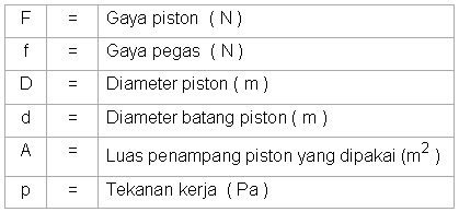
Gaya piston yang dihasilkan oleh silinder bergantung pada tekanan udara, diameter silinder dan tahanan gesekan dari komponen perapat. Gaya piston secara teoritis dihitung menurut rumus berikut :
Untuk silinder kerja tunggal :
Untuk silinder kerja ganda :
Langkah Maju :
Langkah mundur:
Keterangan :
Pada silinder kerja tunggal, gaya piston silinder kembali lebih kecil daripada gaya piston silinder maju karena pada saat kembali digerakkan oleh pegas . Sedangkan pada silinder kerja ganda, gaya piston silinder kembali lebih kecil daripada silinder maju karena adanya diameter batang piston akan mengurangi luas penampang piston. Sekitar 3 – 10 % adalah tahanan gesekan. Berikut ini adalah gaya piston silinder dari berbagai ukuran pada tekanan 1 – 10 bar.
Tabel 2.4. gaya piston
2.2.3.2. Kebutuhan Udara
Untuk menyiapan udara dan untuk mengetahui biaya pengadaan energi, terlebih dahulu harus diketahui konsumsi udara pada sistem. Pada tekanan kerja, diameter piston dan langkah tertentu, konsumsi udara dihitung sebagai berikut :
Untuk mempermudah dan mempercepat dalam menentukan kebutuhan udara, tabel di bawah ini menunjukkan kebutuhan udara persentimeter langkah piston untuk berbagai macam tekanan dan diameter piston silinder.
Tabel2.5. Kebutuhan udara silinder pneumatik persentimeter langkah dengan fungsi tekanan kerja dan diameter piston.

Kebutuhan udara dihitung dengan satuan liter/menit (l/min) sesuai dengan standar kapasitas kompresor.Kebutuhan udara silinder sebagai berikut:
Keterangan :

2.2.3.3. Kecepatan Piston
Kecepatan piston rata-rata dari silinder standar berkisar antara 0,1-1,5 m/s (6 – 90 m/min). Silinder khusus dapat mencapai kecepatan 10 m/s. Kecepatan silinder pneumatik tergantung :
1.      Beban ( gaya yang melawan silinder ).
2.      Tekanan kerja
3.      Diameter dalam dan panjang saluran antara silinder dan katup kontrol arah
4.      Ukuran katup kontrol arah yang digunakan.

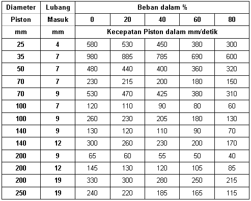
Kecepatan piston dapat diatur dengan katup pengontrol aliran dan dapat ditingkatkan dengan katup pembuang cepat yang dipasang pada sistem kontrol tersebut. Kecepatan rata-rata piston tergantung dari gaya luar yang melawan piston (beban) dan ukuran lubang aliran dapat dilihat seperti pada tabel berikut :
Tabel 2.6 kecepatan piston
2.2.3.4.  Langkah Piston

Langkah silinder pneumatik tidak boleh lebih dari 2 m, sedangkan untuk silinder rodless jangan lebih dari 10 m. Akibat langkah yang panjang, tekanan mekanik batang piston dan bantalan menjadi terlalu besar. Untuk menghindari bahaya tekanan, diameter batang piston pada langkah yang panjang harus sedikit lebih besar.

Kekuatan Material

MECHANICS - CASE STUDY SOLUTION


Cylindrical Gas Storage Tank
 
A gas storage tank needs to be designed to hold pressurized gas at 10 MPa. The tank inside diameter is set at 34 cm due to tank stacking system on a rail car. For safety reasons, a factor of safety of 2.0 is required. The material is steel with a yield stress of 250 MPa. The thickness of the material needs to be determined.
To account for the stress interaction between the hoop and axial directions, the maximum distortion energy theory (von Mises' Yield Criterion) will be used to predict failure.
It is assumed that the end caps will not fail and only the cylinder middle section will be considered (end cap stresses are complex and not studied in this eBook).
          Hoop and Axial Stresses

   
Functions for the hoop and axial stress can be determined for a cylindrical pressure vessel. These are
     σh = Pr/t = (10 MPa)(0.17 m)/t = 1.7/t
     σh = Pr/(2t) = (10 MPa)(0.17 m)/(2t) = 0.85/t
Both the stresses are functions of t.
          Failure Criteria


Stress Element at Cylinder Section  
The maximum distortion energy criteria takes into consideration stresses in multiple directions. The equation is
     
or for this case,
     
The yield stress is given as 250 MPa. However, to account for a factor of safety of 2.0, the actual yield stress is reduced in half. Substituting into the failure equation gives,
     
     2.890 + 0.7225 - 1.445 = 15,625 t2
     t = 0.1178 m = 11.78 mm


MECHANICS - THEORY

    Failure Thoeries


Uniaxial Stress-Strain Curve with
Yield Stress and Ultimate Stress

 
If all structures where loaded in only one direction, it would be easy to predict failure. All that would be needed was a single uniaxial test to find the yield stress and ultimate stresslevels. If it is a brittle material, then the ultimate stress will determine failure. For ductile material, failure is assumed to be when the material starts to yield and permanently deform.
However, when a structure has multiple stresses at a given local (σx, σy and τxy for 2D as discussed in Stresses at a Point section), then the interaction between those stresses may effect the final failure. This section presents three basic failure theories that can be used for different types of materials to help predict failure when multiple stresses are applied.
For simplification, all theories are based on principal stresses (σ1, σ2) which can be determined from any (σx, σy and τxy) stress state. This removes the shear stress terms since the shear stress is zero at the principal directions. Using principal stresses does not change the results from the failure theories.
          Maximum Normal Stress Theory


Maximum Normal Stress Criterion
(Blue Regoin is Safe)  
The simpliest theory ignores any interaction between the normal principal stresses, and assumes that failure occurs when either of the normal stresses exceed the ultimate stress. This is written as


This can be visualized on a plot by normalizing the two normal stress as σ1/σult and σ2/σult. This gives a square region where the stress state is safe. Outside the region is failure.
This failure criteria is really good for brittle materials and should not used for ductile material like steel, aluminum, and plastics.
          Maximum Shear Stress Theory
(Tresca's Yield Criterion)


Maximum Shear Stress Criterion
or Tresca's Yield Criterion
(Blue Regoin is Safe)  
The maximum shear stress assumes failure occurs when the maximum shear stress exceeds the shear stress in a simple uniaxial test. In a unixial test, the principal stresses are σ1 = σx (axial direction) and σ2 = 0 (transverse to axial direction). Using the stress transformation equations, the maximum shear stress for this stress state is
     τmax = (σx - σy)/2 = σx/2 = σyld/2
Thus, for any combination of loading for σ1 and σ2, the shear stress cannot exceed = σyld/2. This condition gives three seperate possible situations that need to checked,


This criteria is actually fairly accurate for ductile materials like steel, alumunim and plastics. The difficulty is that three conditions need to be checked.
          Maximum Distortion Energy Theory
(von Mises' Yield Criterion)


Maximum Distortion Energy Criterion
or von Mises' Yield Criterion
(Blue Regoin is Safe)  
The third theory looks at the total energy at failure and compares that with the total energy in a unixial test at failure. Any elastic member under load acts like a spring and stores energy. This is commonly called distortational energy and can be calculated as
     
The G is the shear modulus. The distortion energy for a general stress state can be compared to distortion energy for a uniaxial test that fails at σx = σ1 = σyld. This gives,
     
Thus the general criterion for failure would be


This criteria is especially useful since it is a single equation. It is also accurate for ductile materials. The shape of the region is an ellispe that is rotated 45 degrees.
      

MECHANICS - THEORY


  Maximum and Minimum Normal Stress


Rotating Stresses from x-y Coordinate
System to new x'-y' Coordinate System


Rotating the stress state of a stress element can give stresses for any angle. But usually, the maximum normal or shear stresses are the most important. Thus, this section will find the angle which will give the maximum (or minimum) normal stress.
Start with the basic stress transformation equation for the x or y direction.
     
To maximize (or minimize) the stress, the derivative of σx′ with respective to the rotation angle θ is equated to zero. This gives,
     dσx′ / dθ = 0 - (σx - σx) sin2θp + 2τxy cos2θp = 0
where subscript p represents the principal angle that produces the maximum or minimum. Rearranging gives,


Principal Stresses, σ1 and σ2,
at Principal Angle, θp 
The angle θp can be substituted back into the rotation stress equation to give the actual maximum and minimum stress values. These stresses are commonly referred to as σ1 (maximum) and σ2 (minimum),


For certain stress configurations, the absolute value of σ2 (minimum) may actually be be larger than σ1 (maximum).
For convenience, the principal stresses, σ1 and σ2, are generally written as,


where the +/- is the only difference between the two stress equations.
It is interesting to note that the shear stress, τx′y′ will go to zero when the stress element is rotated θp.
          Maximum Shear Stress


Maximum Shear Stresses, τmax,
at Angle, θτ-max

 
Like the normal stress, the shear stress will also have a maximum at a given angle, θτ-max. This angle can be determined by taking a derivative of the shear stress rotation equation with respect to the angle and set equate to zero.


When the angle is substituted back into the shear stress transformation equation, the shear stress maximum is


The minimum shear stress will be the same absolute value as the maximum, but in the opposite direction. The maximum shear stress can also be found from the principal stresses, σ1 and σ2, as
     
          Plotting Stresses vs Angle


Stresses as a Function of Angle
 
The relationships between principal normal stresses and maximum shear stress can be better understood by examining a plot of the stresses as a function of the rotation angle.
Notice that there are multiple θp and θτ-max angles because of the periodical nature of the equations. However, they will give the same absolute values.
At the principal stress angle, θp, the shear stress will always be zero, as shown in the diagram. And the maximum shear stress will occur when the two principal normal stresses, σ1 and σ2, are equal.
     
MECHANICS - THEORY

    Combined Stress (or Loads)

Stresses at a point (Stress Element)
for a Cantilever Beam
(Element on Beam is Movable)  
In the previous sections, both the bending and shear stresses were presented for beams. Recall, the bending stress will cause a normal stress (either tension or compression, depending on vertical location) and the shear stress will cause a tearing stress. Both of the stresses can act at the same point and should be considered at the same time. Since only linear elastic materials are considered in this eBook, both stresses can be added together using the principle of superposition. This is shown at the left on a square element called a 'stress element'. This element is really just a point, but to see the stress direction, the point is shown as a square element.


  Stress Element


Stresses at a point (Stress Element)
for Pressurized Pipe

 
The beam above is just one possible configuration for multiple stresses acting at a point. Another possibility is a pipe that is pulled, pressurized and twisted at the same time. These three loads on the pipe will cause tension normal stress in both directions (axial and circumferential) and cause a twisting or shear stress. All three loads and their associate stresses can be combined together to give a total stress state at any point.
The stress element for this example is shown at the left. This section will examine a stress element to better understand stresses at a point and how they can be analyzed.
          Sign Convention for Stress Element


Sign Convention for Stress Element
Positive Directions  
The sign convention for stresses at a point is similar to other stresses. Normal tension stress in both the x and y direction are assumed positive. The shear stress is assumed positive as shown in the diagram at the left. Shear stress act on four sides of the stress element, causing a pinching or shear action. All shear stresses on all four sides are the same, thus
     τxy = τyx
        Stress Rotation


Stress on an Inclined Plane

 
In the Normal Stress section, stress on an inclined plane was presented. It was noted that stresses are not vector quantities, and are not rotated by just using a single sin or cos function. For the normal and shear stress on an inclined plane, the rotated stresses were found to be


Rotated Stress Element  
Similarly, the stresses at a point (stress element) can also be rotated to give a new stress state at any particular angle. The rotation angle, θ, is assumed positive using the right hand rule (counter-clockwise in the x-y plane is positive). The new coordinate system is labeled as x' and y'. The new rotated stresses are shown in the diagram at the left. The shear stresses, τx'y' and τy'x, are still equal.
     

Plane Section through Stress Element


Surface Area on Stress Element Plane

 
The objective is to relate the new stress in x' and y' coordinate system to the original stresses in the x and y coordinate. To do this, the original stress element is sliced at an angle θ, as shown in the diagram at the left. The stresses on the cut plane must be in equilibrium with the stresses on the outside surfaces of the stress element. Remember, nothing is moving, so all stresses and their associated forces must obey static equilibrium equations, ΣF = 0 and ΣM = 0.
Before the stresses are actually summed, the area on each surface needs to be defined. The plane section at the angle θ is assumed to have a basic area of dA. The stress element is really just a point, so the area is infinitesimal, or just dA. The other two surfaces are based on dA. The bottom surface will be 'sinθ dA' and the left surface will be 'cosθ dA', which are shown in the diagram at the left.
Summing the forces in each direction gives
     ΣFx = 0 = (σx´ dA) cosθ - (τx´y´ dA) sinθ
                           - σx (cosθ dA) - τxy (sinθ dA)

     ΣFy = 0 = (σx´ dA) sinθ - (τx´y´ dA) cosθ
                           - σy (sinθ dA) - τxy (cosθ dA)

There are two unknowns, σx´ and τx´y´ and two equations, so they can be determined, giving
     σx´ = σx cos2θ + σy sin2θ + 2 τxy sinθ cosθ
     τx´y´ = - (σx - σy ) sinθ cosθ +τxy (cos2θ - sin2θ)
The y' direction can be developed in the same way, but the section plane is 90o offset. The final equation is
     σy´ = σx sin2θ + σy cos2θ - 2 τxy sinθ cosθ
     
Rotated Stress Element  
Using double angle trigonometry identities, these three equations can be simplified to


          Stress Rotation Plot


Stress Rotation Tool   To help visualize how the stress changes when the stress element is rotated, the simulation at the left plots σx´σy´ and τ x´ y´ as a function of the angle. Notice, the period is 180o. The initial stress state can be changed.